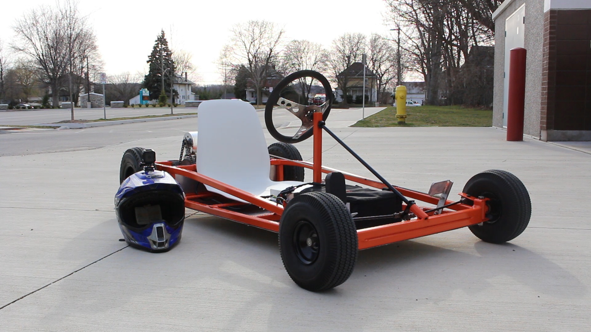
To eliminate or avoid warping the plate, or causing Check the joint fit and tack weld in place. Step 19: Position these tubes on the go kart frame as Cut a length of tube for part number WP-908-11. Step 18: Cut and prepare the ends of part number WP-908-12 (qty 2). Special care should be taken to assure they are correct on the frame before and after welding. The position, placement, and angle of these parts also affect the tracking and steering of the go kart. Step 17: Weld WP-908-16 in place one at a time as indicated on the drawing. Note: use the flat pattern dimensions when cutting the parts out of the sheet. Bend the plates as indicated on the drawing. Step 16: Cut part number WP-908-16 (qty 2) from the 11 GA sheet. Once this has been assured, complete the welds. The position, placement, and angle of these parts directly effect the tracking: and steering of the go kart.

Tack weld each tube at the correct angle, making sure both parts are in-line with part number WP-908-6 (front crossmember). Position each part (one at a time) on the frame and check the fit. Recheck placement and fit and complete the welds. Tack weld in place at both ends of the tube. Step 14: Position the roll-over bar on the frame according to the drawing. Step 13: Cut a length of tubing and bend according to the drawing to make part number WP-908-4. Complete the welds at each joint, alternating from one side of the frame to the other. Make sure the frame bottom is still flat on the work surface. Step 12: Tack weld each tube at the joints. Step 9: Repeat on the other side of the frame bottom. Make sure this tube is vertical and perpendicular to the long side of the bottom frame. Position a WP-908-10 on one side of the frame bottom as indicated on the drawing. Clamp it in place, or place weights on top so it will not move easily. Step 8: Place the frame bottom, WP-908-2, on the flat work surface. Always check the fit of the tube where there is contact with another tube, in other words, at the joints.

It won’t take long to get a feel for how much to grind. Be sure to work slowly and check the fit often. It is advisable to practice first on a piece of scrap tubing. After the grinding wheel face has been shaped (radiused), the tube end can be formed by holding the end of a tube at the correct angle while grinding a concave or “fish-mouth” necessary to create the joint geometry. The width of the grinding wheel must equal the diameter of the tubing to which the part will mate- in this case, ¾”.

It is done by using a dressing wheel to create a radius to the face of a grinding wheel. This is a common method of creating a “Fish-mouth” in the ends of tubing used in aircraft construction. An effective method of preparing these tube ends for the joint is by forming them on a bench grinder. This is due to the limited travel distance of the hole saw. Step 6: Most hole saw tools will not make long, shallow cuts like the ones at the ends of part number WP-908-3. Step 5: Similar to the above steps, make the necessary bends to create part number WP-098-3. Step 4: Cut the length of tubing for part number WP-908-3. Make sure the “frame bottom” lays flat on the work surface before and after it is welded. This should be a flat weld bead all the way around the tube. Step 3: Weld the ends of the tube rectangle together. Make sure the tube ends are within a 1/16” from each other and facing each other in the middle of one of the shorter legs of the rectangle, as noted on the drawing.

This will be the bottom of the go kart frame.Īfter all bends are made, this part will be a rectangle. Step 2: Using a tube bender with a ¾” X 4” bending die, make the bends in the tube to create part number WP-908-2 as shown on the drawing. Step 1: Referring to the cut list on page one of the drawing, cut a length of ¾” X.
#DIY GO KART FRAME PDF#
Or you can get the one page pdf version of the above weldments here in PDF format.Ģ4 Steps To Building A Killer Go Kart Frame! You can get more detailed 22 page PDF set of this go kart frame plan set here.This is best done before any bends are made, while the tube is resting in the bending die. This can be accomplished by adjusting the height of a take-up table or surface to correspond to the bottom of the tube. Otherwise, the tube form may become unusable. Whenever you make more than one bend in a tube form that must remain flat, pay particular attention to the plane of the tube prior to each bend.However, if either TIG or the Oxy processes are used, the weld joints need to be particularly tight. This project is intended to be completed using either MIG, TIG, or Oxy-Acetylene weld processes.


 0 kommentar(er)
